AWS Private Link – Shared Resource for Multi VPC

Setting up a common resource across different environments is always a redundant task, It not only incurs cost , it also takes time to test and validate the same , one such use case we see with is setting up a  License server with every new environment ( prod1, prod2 etc  ) , This redundant server setup problem can be solved , if the license server can be deployed as a shared resource and consumed from different environments deployed in different VPC’s.  

There are different solutions to solve the problem,  AWS private link is one solution for the same, it helps in setting up a shared resource in one VPC and provide  access to the client / environment configured  in another VPC without compromising on security and not exposing the traffic over internet.

More Info –   AWS private Link  – https://aws.amazon.com/privatelink/

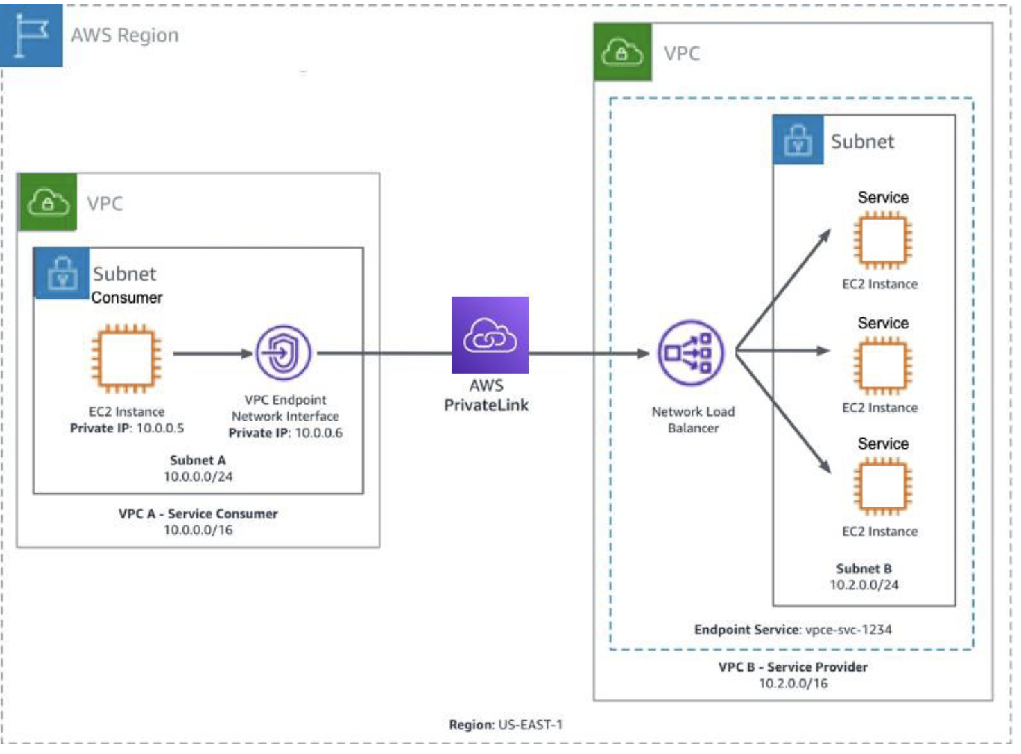
AWS private link  can be configured using the following two VPC resources.

1) Endpoint Service ( Producer side  ,  used for exposing the shared resource via a Network load balancer- NLB )
2) Endpoint (Consumer  side, used for consuming the shared resource exposed using Endpoint service via a  Elastic Network interface – ENI  )

Endpoint service and Endpoint can be configured in different VPC’s within the same region Let’s see how an Endpoint Service and an Endpoint can be configured

Endpoint service (Producer side)

1) Endpoint service configuration can be done in any shared environment which can be consumed by different clients / environments.
2) Network Load Balancer ( NLB ) is a prerequisite for creating endpoint service and need to be configured with Endpoint service.
3) NLB can configured to the target where the shared resource is deployed.
4) In the current License server setup, license server is installed on EC2 as NLB target.

Endpoint Service Creation :

1) Go to VPC console, Select Endpoint Service from the left panel
2) select Endpoint and provide the required configuration.

Endpoint  ( Consumer side  )

Endpoint configurations need to be done on the consumer side for consuming the shared resource.
Endpoint requires the name of Endpoint Service.

Elastic Network Interface ( ENI ) is created and attached to Endpoint once the endpoint is created.    
Private IP address of the ENI acts as interface for accessing the shared resource exposed through Endpoint service.                                                                                                                                                                                                                      
Endpoint Creation :

1) Go to VPC  console , Select End point from the left panel as follows   
2) Select Endpoint and provide the required configuration as follows
2.1) select other endpoint service and give the name of the service ( this is name of the endpoint service , Eg: com.amazonaws.vpce.us-east-1.vpce-svc-XXXXXX) to be consumed.
        2.2) Click submit once the endpoint service name is given ,  once done with submit an Endpoint ( Interface Type ) is created along with a  Network Interface as shown below.
        2.3) Once Endpoint is created , it will not be ready to use, it requires an additional step of  approving respective endpoint from endpoint service console. After End point is approved from End point service , the status of Endpoint is shown as Available , until then we will see the status as Pending for approval Once the end point status is Available , end point is ready to be consumed using the private IP address of the Network interface created along with the End point.

** Private  IP address  of network interface used for consuming the shared endpoint service.  

Linking  Endpoint to Endpoint service –

1) Once Endpoint Service and Endpoint is configured, next step is to link Endpoint to Endpoint service for consuming the shared resource hosted on Endpoint Service.  
2) For approving Endpoint from Endpoint service, go to  Endpoint Service -→  Endpoints tab ,  select the respective endpoint and click on action and approve the End point.
3) Once done  , endpoint is ready to be consumed using the private IP address of the elastic network interface ( ENI ).  

Accessing Shared resource  –

Once Endpoint Service  and Endpoint are configured , clients  can access the shared service hosted with Endpoint service using Elastic Network Interface ( ENI ) private IP address created with Endpoint.

Accessing Centralized License Server:

our App makes use of Docker plugin for accessing the Licensed server.

docker plugin discovers the Licensed server using predefined IP , therefore following additional steps are required for accessing the centralized license server.

Launch a t3.nano machine  which acts as a proxy machine to connect to Endpoint.
Have a predefined IP – xxxx for the proxy machine  , This is a predefined IP configured for plugin for discovering the licensed server.  

To access the centralized license server from  the proxy machine,  Tunnel is configured  between Proxy machine and ENI  as follows

The Linux utility simpleproxy can be used to setup the proxy, once the utility is installed you can use the following command to setup the proxy.  

Eg : simpleproxy -L portno -R x.x.x.x:portno

x.x.x.x is  the IP address of the Network interface which will be pointing to the centralized server configured using AWS private link.

portno is port on which license server is listening for the incoming license requests.

Tunnel is setup as a service on the proxy machine using the following steps to make sure it’s up and running even after system restarts.

install simpleproxy  utility , more info on the untility  :  https://manpages.ubuntu.com/manpages/kinetic/en/man1/simpleproxy.1.html

usage of simpleproxy command

simpleproxy -L [local port on which you want to listen for remote requests] -R [remote host:remote port for which you want to proxy/tunnel to]

once simple proxy is installed , create a file named simpleproxy.sh  in /tmp  and add the following content.

simpleproxy -L 22350 -R 10.0.26.109:22350

Go to the directory :   cd /etc/systemd/system
Create a file named xxx-service.service and include the following

[Unit]
Description=xxx service

[Service]
User=root
WorkingDirectory=/tmp
ExecStart=/tmp/simpleproxy.sh
Restart=always

[Install]
WantedBy=multi-user.target
save the above file and then start the service using the following command.
systemctl start xxx-service.service

Once complete above configuration is in place ,  we are good to validate the centralized license server.


AWS Blue Green Deployment

A blue/green deployment is a deployment strategy in which you create two separate, but identical environments. One environment (blue) is running the current application version and one environment (green) is running the new application version.

With one of our current environments, the way we upgrade the DB is self-managed and this is tedious and takes a reasonable amount of downtime, this is not acceptable for certain clients (Eg xxx cannot afford more outage).  Apart from downtime, there is a chance for manual errors, as this is self-managed. This problem can be avoided if we have an automated blue green deployment, where it can greatly eliminate the duration of downtime and avoid any manual errors, also if any unexpected error happens with the updated version, say green, we can immediately rollback to the last working version blue.  

With AWS RDS Blue Green deployment, this complete deployment process is  automated with an average downtime of 2 seconds ( downtime can increase based on the amount of data to be replicated and live production traffic, more inputs provided under replica lag section below  ). This can provide an uninterrupted service to the clients with a very minimum outage. 

Let’s  consider the following AWS RDS Deployed in a Single AZ and upgrade to an higher version using  AWS  Blue Green deployment.

Amazon RDS Blue Green Deployment 

By using Amazon RDS Blue/Green Deployments, we  can create a blue/green deployment for managed database changes. A blue/green deployment creates a staging environment that copies the production environment. In a blue/green deployment, the blue environment is the current production environment. The green environment is the staging environment. The staging environment stays in sync with the current production environment using logical replication.

AWS Blue Green deployment helps in all the following use cases. 

  • Major/ Minor version upgrades
  • Schema changes
  • Instance scaling
  • Maintenance updates
  • Engine parameter changes

Blue Green deployment is a Two step process 

  • Step – 1 Create a Blue/Green environment.
  • Step- 2 Switchover to Green environment. 

Step 1 – Create  Blue/Green environment 

  • Select DB( refereed as Blue environment ) which needs to be upgraded.  
  • Go to actions – Create Blue/ Green Deployment. 
  • Provide the following basic configuration
    • Name of the staging environment. 
    • Version of DB to be upgraded. 
    • DB parameter group ( same as prod db parameter group, fine tuning the parameters can reduce the replica lag , more explained in the section Replica Lag below )
  • once submitted, the above configuration creates a copy of the current production environment with a logical data replication. 
  • Traffic will still be flowing through blue environment and data is replicated to Green environment.   


Blue/ Green Deployment RDS configuration 

  • Blue label – Current production environment.
  • Green label – Target Environment.
  • Staging – Logical representation of blue green deployment ( not  a DB instance on its own )

Step 2 – Switch Over

  • Once the Green environment is tested and validated,  the next step is to switch over to the Green environment.
  • Select staging and go to Actions and select the option Switch Over.  
  • Once Switchover is selected, it goes through different steps for switchover
    • Typically it takes one minutes to switch over. 
    • Constantly monitors the health of both blue and green. 
    • Configurable RTO is provided – which rolls back the entire migration if there is any issue with migration , this helps to fail safely. 
    • During this switch over,  we can still have read operations. 
    • Blocks write on blue  and allow green to catch up and then a final switchover is done towards green. 
  • At the end,  once the switchover is done, the entire traffic is redirected to Green environment.  
  • We don’t need any change on the client code, the endpoint remains the same and clients will start  interacting back with the new production green environment as is. 
  • In the interest of safety , the old DB which is a blue environment is not deleted and renamed to -old , we need to manually delete the blue environment or we can keep it as a backup for any further validations.  

Final State after Switchover 

  • Blue DB which is current production environment is renamed to prod-old 
  • Green DB is renamed to prod , which will be the same name as  your current production environment. 

 Multi AZ  RDS Blue green Deployment 

The same entire above flow with Blue Green deployment is validated with Multi AZ  RDS instances and following is the glimpse of the Blue Green environments deployed in Multi AZ. 

Down Time 

  • In a  Single AZ deployment , switch over took 48 seconds  with a test DB. .  
  • In a Multi AZ , switch over took 68 seconds 
  • During this down time any write operations are blocked  and  will result in error – “The MySQL server is running with the –read-only option so it cannot execute this statement” , read operations can still be resumed. 

Replica Lag 

Limitations

  • Available on Amazon RDS for MySQl versions 5.7 and higher.
  • Cross-Region read replicas
  • Amazon RDS Proxy
  • The resources in the blue environment and green environment must be in the same AWS account.
  • More – Blue Green Deployment Limitations

Considerations 

  • During testing, it’s  recommended to keep your databases in the green environment read only. It’s recommended that you enable write operations on the green environment with caution because they can result in replication conflicts in the green environment. They can also result in unintended data in the production databases after switchover.
  • The switchover results in downtime. The downtime is usually under one minute, but it can be longer depending on your workload.
  • The name (instance ID) of a resource changes when you switch over a blue/green deployment, but each resource keeps the same resource ID. For example, a DB instance identifier might be mydb in the blue environment. After switchover, the same DB instance might be renamed to mydb-old1. However, the resource ID of the DB instance doesn’t change during switchover. So, when the green resources are promoted to be the new production resources, their resource IDs don’t match the blue resource IDs that were previously in production
  • When using a blue/green deployment to implement schema changes, make only replication-compatible changes For example, you can add new columns at the end of a table, create indexes, or drop indexes without disrupting replication from the blue deployment to the green deployment. However, schema changes, such as renaming columns or renaming tables, break binary log replication to the green deployment. (https://dev.mysql.com/doc/refman/8.0/en/replication-features-differing-tables.html )

Post Activity : 

  • Pay attention to  channel for any alerts
  • Check Dashboard for any abnormal Activities 
  • Check alerts for error logs
  • check if sudden burst of non-200s
  • look at certain DB metrics 
  • Make sure all the DB parameters are reset back to original values.